- Products & Capabilities

- About
- Resources
Essential Files for PCB Fabrication


Creating a PCB involves detailed files like Gerber, NC Drill, BOM, Centroid, Readme, and Dimension Drawings. These files ensure precise design communication and minimize manufacturing errors.
The process of creating a printed circuit board is complicated and involves various detailed files for production. These files give critical information regarding the design of the PCB, its components, layers, and specifications. The maximization of the documentation in an effort to avoid any potential errors is very instrumental in making the manufacturing process easy. In the article, we describe the main files necessary for the manufacture of a PCB and explain what's important about them.
Gerber Files
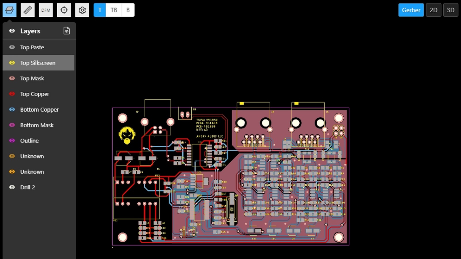
Gerber files are the standard for PCB manufacturing, describing individual layers of the PCB in a graphical format that manufacturers use to fabricate the board. Each layer of the PCB design gets converted into a separate Gerber file.
- Copper Layers: Top and bottom copper traces; internal layers on multilayer boards that define the electrical connections of your PCB.
- Solder Mask Layers: These layers for top and bottom outline areas that should either have solder mask applied to, or from.
- Silkscreen Layers: Component labels, logos, and any other markings on both the top and bottom of the PCB.
- Paste Layers: These are required for SMD—Surface Mount Device Assembly. They specify the areas where solder paste should be applied.
- Board Outline: It describes the dimensions, shape, and physical form of the PCB.
NC Drill File
The NC (Numerical Control) Drill file contains information on all the holes to be drilled into the PCB. These can include vias, through-hole component leads, and mounting holes.
Contents:
Hole positions
Hole sizes
Hole types
Plated or Non-plated
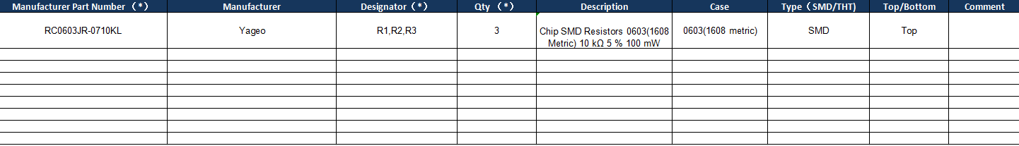
Bill of Materials (BOM)
BOM-PCBX
The BOM includes a detailed list of all components used to build the PCB, including:
Component reference designators (e.g. R1, C2)
Part numbers
Component descriptions
Quantities
Manufacturer or supplier details
Centroid File
The Pick and Place file or Centroid file, contains all of the SMD's positions and orientations on the PCB.
contents:
X and Y coordinates of each component
rotation angles
Reference designators
Layer information, top or bottom
Readme or Assembly Drawing
Though not required, it is very helpful to include a Readme file or an Assembly Drawing. These can contain details such as:
Board stack-up
Special instructions or notes
Component placement details
Layer descriptions
Dimension Drawing
The Dimension Drawing ensures that the PCB will physically fit within its intended enclosure or application, ensuring that there are no mechanical fit issues. Details include mechanical dimensions of the PCB containing:
- Outline of the board
- Position and size of holes
- Any cutouts or slots
Conclusion
A full set of files for PCB fabrication ensures the accuracy and quality of manufactured boards. Gerber files, NC Drill files, BOMs, Centroid files, Readme or Assembly Drawings, and Dimension Drawings all provide specific design information in the process of communicating with the manufacturer. This could be done by making sure there is careful preparation of these documents and that the guidelines of the manufacturers are followed. It greatly lessens the possibility of error in the PCB fabrication process.
Hot Tags:

Contact us

If you can't find what you're looking for, please contact us.
Article
PCBs (Printed Circuit Boards) are fundamental in electronics, composed of multiple layers like silkscreen, soldermask, copper, and substrate, chosen for specific electrical functions.
 2024/08/07
The article is developed concerning the breakthrough of integrated circuits and the need for custom PCBs in some electronic products. It enumerates ten golden rules in conducting PCB layout design and manufacturing: grid selection, routing, power layers, component placement, panel duplication, component value combination, frequent DRC, flexible silkscreen use, decoupling capacitors, and pre-production parameter checks. These rules provide for the optimum design and manufacturing of a PCB.
2024/07/25
Most electronic circuits are mounted on PCBs, or Printed Circuit Boards, which provide mechanical support and electrical interconnection of electronic components. There are, however, special applications that involve the use of single and double-sided PCBs, multi-layer PCBs, or even rigid and flexible PCBs with aluminum backing, targeting medical, industrial, auto, and aerospace industries. They may use materials such as fiberglass, epoxy, aluminum, and others.
2024/07/25